| Nama merek: | Sinuo |
| Nomor Model: | SNQC1001 |
| MOQ: | 1 |
| harga: | Customized |
| Ketentuan Pembayaran: | T/T |
| Kemampuan Penyediaan: | 5 set per bulan |
Vehicle Rain Leakage Testing Equipment Car Rainproof Sealing Test Chamber
Complied Standards & Clauses
Conforms to IEC 60529 Degrees of protection provided by enclosures (IP Code);
Product Overview
This automotive rain test chamber simulates natural outdoor rain conditions to set up spray testing conditions. All surfaces of a motor vehicle potentially exposed to rain are sprayed. After the specified time, testers record and score the leakage patterns (seepage, slow drip, drip, fast drip, and flow) in various compartment areas. This ensures the vehicle's outdoor water tightness and allows for structural improvements to be implemented in areas with potential leaks.
This automotive rain test chamber utilizes PLC intelligent central integrated control with a computer interface for display and operation. Test data can be printed and edited in the form of actual test reports. Parameters are set through a computer interface, the spray test process is fully automatic, and the front, rear, and top spray mechanisms are adjustable to match vehicles of various specifications. It is the preferred reliability equipment for third-party testing agencies and factory laboratories.
Technical Parameters
| No | Item | Content |
| 1 | Power supply | AC380V 50Hz 15kW, and requires an air-powered switch with a leakage protection device |
| 2 | Test vehicle specifications |
Dimensions range: Length 3000mm-5000mm, Width 1700mm-2000mm, Height 1600mm-2000mm |
| 3 | Test items |
1. Passenger bus rain test as specified in QC/T476-2007 "Limits and Test Methods for Rainproof Sealing of Passenger Buses" 2. GB/T12480-2009 |
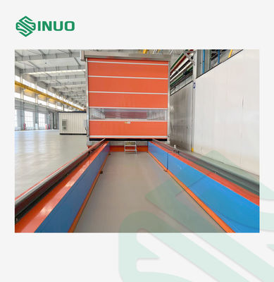
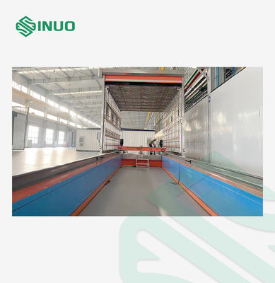
| 4 | Rain chamber | LWH=12.0m×3.5m×3.0m, steel frame, warehouse structure, including spray section and drain and dry section, of which the spray section is 7.0m long and the drain and dry section is 5.0m long |
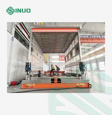
| 5 | Doors and Windows | The shower room adopts a full-body structure, with front and rear door dimensions of 3.5×2.7m, and symmetrical windows on both sides with multiple panels of 1.2×0.8m, using 8mm tempered glass or acrylic transparent panels. |
| 6 | Rain intensity |
Front rainfall intensity: 12 ± 1 mm/min adjustable Upper rainfall intensity: 8 ± 1 mm/min adjustable Side rainfall intensity: 8 ± 1 mm/min adjustable Bottom rainfall intensity: 8 ± 1 mm/min adjustable |
| 7 | Nozzle | The nozzle diameter is 2.5~3mm, and the end is rounded 60°. |
| 8 | Nozzle layout | The horizontal and vertical center distance is 400×400mm, and the rain test area is covered in a matrix form |
| 9 | Spray direction |
The vehicle's left and right sides, top, bottom, front, and rear—a total of six surfaces. The top and bottom nozzle axes are perpendicular to the horizontal plane, the front and rear nozzle axes are parallel to the vehicle's longitudinal symmetry plane, and the side nozzle axes are perpendicular to the vehicle's longitudinal symmetry plane. |
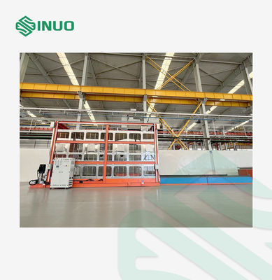
| 10 | Distance between nozzle and vehicle | The bottom nozzle is located 200mm below the ground and is fixed in position. Other nozzles are located 700±200mm from the vehicle's exterior. Branch pipes for each nozzle installation are modularly fixed to the bracket. The distance between the spray mechanism and the vehicle's exterior can be adjusted on all surfaces, except the bottom and two sides, to meet standard requirements and accommodate different vehicle sizes. |
| 11 | Rain time | 0-99h59min59 s presettable |
| 12 | Test flow | Calculated according to the standard formula (Q=6FN/625 or Q=3FNS/50), flow control valve adjustment, electronic flow meter collection feedback, computer display |
| 13 | Water supply pressure | 69-200±10kPa, adjustable, using pressure sensor to monitor and collect data |
| 14 | Spray mechanism pipeline |
Pressure gauges and flow meters must be installed on each branch pipe and main pipe. Rainfall intensity must comply with the national standard QC/T 476-2007. Flow meters must be high-quality, domestically produced. The installation locations of flow meters and pressure gauges must comply with national standards, and the pressure gauge range and accuracy must meet the control plan and process requirements.
Each branch pipe must have a drain outlet at the end and a plug installed to ensure a tight seal. The plug should be made of SUS304 stainless steel.
(Pipeline dimensions are subject to actual production.) |
Details
![]()
![]()